
Feature Project
Ultrasonic Rangefinders in Film

In the world of film and television, every shot you see on the silver screen is kept in focus by the most advanced system available; humans. Given the high level of accuracy required over a wide range of subjects, situations, lighting, and camera systems, traditional autofocus simply can't cut the mustard when compared to a human operator manually "pulling"
focus throughout each scene. To help aid this process, systems such as the CineTape have been invented that use ultrasonic sensors to determine the distance an object is away from the front of the camera. The focus puller then uses this information to keep the shot in focus regardless of how much the actors or camera moves.
As a working 1st AC, the responsibility of keeping the shot in focus frequently falls on me, regardless of whether I have access to tools like the CineTape that ensure my distance measurements are accurate. To help alleviate this issue, I decided to design my own ultrasonic rangefinder system that will provide accurate distance information in a small form-factor. To do this, I needed to design a system that could take measurements of a human target accurately up to ~15ft away and display that information in an easily readable format. Furthermore, this device has to be able to draw power from the existing camera's battery to maintain simplicity and versatility.
Components
The development platform I chose was the very popular open-source Arduino board that allows for numerous digital and analog inputs/outputs plus low power consumption. The added benefit to this platform is the availability of the Arduino Nano board that retains the same functionality as the full-sized kit in a much smaller package, helping keep the rangefinder's size to a minimum.
The next step was determining what ultrasonic sensor I would use for this project since accuracy over a long distance was crucial given the use-case I had in mind. For this, I turned to sensor maker Maxbotix given their small size and ease of use. The mechanics behind an ultrasonic sensor are simple; send out a pulse of high-frequency sound and then measuring the time it takes for the echo to return. From a technical perspective, this is done by calculating the speed of sound in the given environment (based on temperature) and then dividing the resulting flight time of the soundwave by two to get the final distance since the sound waves are traveling to the object and then back.
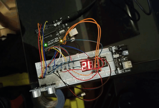
Wiring

With my development board and sensor chosen, the next step was wiring the sensor, display, and Arduino together. As this diagram shows, the Arduino is taking input from the sensor and outputting the result to the seven-segment display. To make this process as simple as possible, I have chosen to use the Pulse Width Modulation (PWM) method for measuring the distance which counts the length of each pulse before being converted to inches. This is much simpler than the analog method that measures a difference in voltage generated by the sensor across a 5V circuit. As a result, I get a more accurate reading and slightly simpler code since only one type of input pin is being read. The final ingredient is the power supply which, for the Arduino Nano, will be the 5V 1A mini USB connection that comes built-in. This method of power delivery ensures the rangefinder can be used anywhere while still delivering enough power to supply the board, sensor, and dual seven-segment displays.
Programming
The next step in this process is writing the code that captures, analyzes, and displays the data collected from the ultrasonic sensor. This process starts by taking a reading from the sensor that measures the length of each pulse as echos are received. I can then take this PWM value and divide it against the sensor's default value of 147 μS (microseconds) per inch to get the distance. From here, it's just a simple conversion to get feet, the remainder of which is then stored and used later when outputting the final result to get [ Feet | Inches ] on the display. In future iterations, I plan to add a section of code that will compare the distance values read from the sensor and calculate the median. This should help smooth the transition when a target is moving closer to/away from the sensor.
The final step is outputting this data to the dual seven-segment displays. For this, I have written a small loop that first calculates the value of the distance being returned. If this distance falls below the minimum threshold or rises above the maximum measurable distance for the sensor, it will just display [ - - | - - ]. This makes it very easy to see when an issue has occurred with the rangefinder. Otherwise, if the value is within the proper range, the Arduino will run one last piece of code to make the measurement easily readable on the display. This can be done by overlapping the feet and inches values in addition to removing the zeroes between the two sections. With the seven-segment display driver I am using, this means I must individually define how many digits are in each section, what digit position each section occupies, and whether there are leading zeros. The end result of which will return [ 1 1 | 6 ] from an initial reading of 138 inches.
const int pwPin1 = 2; //Pin 2 for sonar
long sensor, inches, inches2, feet;
#include <Arduino.h>
#include <TM1637Display.h>
#define CLK 3
#define DIO 4
const uint8_t invalid[]={ //Out of range
SEG_G,
SEG_G,
SEG_G,
SEG_G,
};
TM1637Display display(CLK, DIO);
void setup() {
Serial.begin(9600);
display.setBrightness(0x0f);
display.setSegments(invalid);
pinMode(pwPin1, INPUT);
delay(800);
}
void read_sensor () {
sensor = pulseIn(pwPin1, HIGH);
inches = sensor / 147;
feet = inches / 12; //Calculate feet
inches2 = inches % 12; //Calculate remainder
}
void print_range() {
Serial.print("Total");
Serial.print("=");
Serial.print(sensor);
Serial.print(" ");
Serial.print(inches);
Serial.print("in ");
Serial.print(feet);
Serial.print("ft ");
Serial.print(inches2);
Serial.println("in ");
if(inches >= 200){ //Maximum distance
display.setSegments(invalid);
}
else if(inches < 12){ //Minimum Distance
display.setSegments(invalid);
}
else{
display.showNumberDec(feet, false, 2, 4);
display.showNumberDec(inches2, false, 2, 2);
}
}
void loop() {
read_sensor();
print_range();
delay(175);
}
CAD & Printing
After successfully assembling all of the hardware and software, the final stage in this process was designing an enclosure to house all of the components and allow for easy mounting onto any camera. I did this by taking exact measurements of each component and recreating them in my CAD (Computer-Aided Design) program. This allowed me to arrange all of the components digitally before designing the case around them, providing me with a perfect fit after printing. All told, this step became the most time consuming by far because I had to conceptualize the final case being split in half for printing and assembly while designing it. Think of it like trying to paint a detailed origami crane before the paper has been folded. This initial design is just a prototype, and I engineered it to be far larger than necessary to allow for easy testing. In future iterations, I plan on using larger seven-segment displays in addition to threaded inserts for more strength.


Final Product
While this concept still has a long way to go before it can compete with the established brands like CineTape, I am very happy with how it turned out given the time and energy I invested. Moving forward, I will need to experiment with a variety of different sensor pickup patterns to find the sweet spot between sensitivity and accuracy. As of now, the ultrasonic sensor I'm using seems to lean toward sensitivity at the cost of accuracy. This becomes a problem when the rangefinder detects objects outside the camera's field of view. The next improvement I would like to make is utilizing a much larger seven-segment display which should make the distance much easier to read. With these improvements, I plan on redesigning the case from the ground up to accommodate the new parts while cutting down the amount of wasted space, thus reducing the overall footprint of the device. Nonetheless, I consider this project both a resounding success and a massive learning opportunity that pushed me to further develop my skills in electrical engineering, computer programming, and 3D modeling.


